Aiwa CA-DW540 User Manual
Browse online or download User Manual for Cassette players Aiwa CA-DW540. . xiaoyu163. com QQ376315150 99 28 94 29 8
- Page / 43
- Table of contents
- BOOKMARKS
- SERVICE MANUAL 1
- SPECIFICATION 2
- ACCESSORIES PARTS LIST -1/1 4
- ELECTRICAL PARTS LIST - 1/10 5
- ELECTRICAL PARTS LIST - 2/10 6
- ELECTRICAL PARTS LIST - 3/10 7
- ELECTRICAL PARTS LIST - 4/10 8
- ELECTRICAL PARTS LIST - 5/10 9
- ELECTRICAL PARTS LIST - 6/10 10
- ELECTRICAL PARTS LIST - 7/10 11
- ELECTRICAL PARTS LIST - 8/10 12
- ELECTRICAL PARTS LIST - 9/10 13
- ELECTRICAL PARTS LIST - 10/10 14
- 8131 29111214 7 10 16
- MAIN C.B 17
- FRONT C.B 17
- (DECK MOTOR) 18
- MAIN C.B-2/3 (CD SECTION) 19
- MAIN C.B-3/3 (TUNER SECTION) 20
- MAIN C.B FRONT C.B 22
- SENSOR C.B 22
- POWER C.B 23
- MOTOR C.B 23
- FRONT C.B MAIN C.B 24
- IC BLOCK DIAGRAM -1/2 26
- IC BLOCK DIAGRAM -2/2 27
- MECHANICAL EXPLODED VIEW -1/1 34
- MECHANICAL PARTS LIST -1/1 35
- COLOR NAME TABLE 36
- OTHER PARTS LIST -1/1 42
Summary of Contents
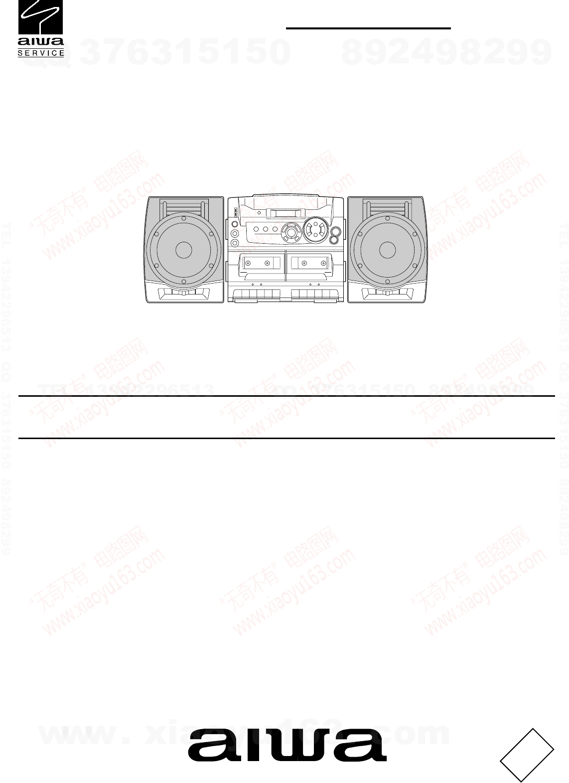
SERVICE MANUALDATACOMPACT DISC CARRYCOMPONENT SYSTEMCA-DW540S/M Code No. 09-025-456-4N2U(ST)• BASIC TAPE MECHANISM: ZZM-2YPR3NC• BASIC CD MECHANISM: K
! = ! SAFTY PARTSC = Components markedAll components used on this model at the production line are shown in this service manual.However, please not
! = ! SAFTY PARTSC = Components markedAll components used on this model at the production line are shown in this service manual.However, please not
! = ! SAFTY PARTSC = Components markedAll components used on this model at the production line are shown in this service manual.However, please not
! = ! SAFTY PARTSC = Components markedAll components used on this model at the production line are shown in this service manual.However, please not
! = ! SAFTY PARTSC = Components markedAll components used on this model at the production line are shown in this service manual.However, please not
-15-TRANSISTOR ILLUSTRATIONEBCECBBCE2SA1162DTA144EKADTC114TKADTC114YKAKRC104S2SA12962SA13182SC18152SC20012SC2240KTC31982SA9332SC1740KRC108MKRC111M2SB1
-16-21 23 19 20 18 17 28 22 27 26 24 25 16 154365IN-AIN-BIN-AIN-BOP IN-OP-IN+VCCSUB-GNDSUB-GNDOP-OUTIN-BIN-AIN-BIN-ABIAS8131 29111214 7 10MOTOR C.BFRO
-17-WIRE HARNESS DIAGRAM-1/1MAIN C.BPOWERC.BFRONT C.BSENSORMOTOR C.BC.Bhttp://www.xiaoyu163.comhttp://www.xiaoyu163.com
-18-SCHEMATIC DIAGRAM - 1/4 (MAIN-1/3, DECK/AMP/POWER SECTION)MAIN C.B-1/3 (DECK/AMP SECTION)POWERC.B3TO FRONT C.BTO FRONT C.B1A2A3A4A5A6A7A1B2B3B4B5B
-19-KRC104S1000P 1000P1000P82K680P5.6K1/5015K47/100.22/50100/101N4148M47/10220/10220/103.3/50100/1047/1015K390100/50220/1010/5010/504.7/50KRC108M1N414
-2-SPECIFICATIONTuner sectionFrequency range, antenna FM: 87.5 - 108.0 MHz Rod antennaAM: 530/531 - 1,710/1,602 kHz (10/9 kHz step) Ferrite bar antenn
-20-SCHEMATIC DIAGRAM - 3/4 (MAIN-3/3 TUNER SECTION)MAIN C.B-3/3 (TUNER SECTION)SIGNALFM RF1000P1.5K5P0.0270.02733P1N4148M1N4148M330PHVC202AHVC202ATP1
-21-SCHEMATIC DIAGRAM - 4/4 (FRONT SECTION)1K1K0.022 0.0221N4148M1N4148M1N4148M1N4148MKRC108MKRC108MKRC108M2SC2240GRVR801MIC1/50100KKRC108MSPS4421F1OU
EBCEBCEBCEBCBECE BCB ECC B1 1222121112 124 13EQ408CN401IC401Q407Q404Q403R456R405R453R408R409C420C405C411R402Q401C437R489R415C433C438D403C439R434R435C4
WIRING - 2/2 (POWER C.B / MOTOR C.B)-23-POWER C.BM1M2SW1M1(SPINDLE MOTOR)SW1(INSIDE LIMIT SW)J901M2(SLED MOTOR)PIN1MOTOR C.B__++TO MAIN C.B CNA4021234
-24-ELECTRICAL ADJUSTEMENT-1/1L004L007IC001L330J251SFR7611367 87RPH/PH82 4459TC00123SFR430C39L006BAR ANTL003L005FRONT C.B MAIN C.B1. AM IF Adjustmen
-25-LCD DISPLAY (HLC7107ACT-9) -1/1http://www.xiaoyu163.comhttp://www.xiaoyu163.com
-26-IC BLOCK DIAGRAM -1/2DECK LDECK LDECK RL OUTR OUTTAPE SELECTDECK RSW/LWMW/FM1MUTEIF MUTEMONO/BEATAM10A-GNDIC, BA3416BL IC, M62495AFPI
-27-1 2 3 4 5 6 7Level shift10k13kT.S.D10k10k50k50k28 27 26 25 24 23 22Level shift10k13kVcc21 20 19 18 17 16 15VccLevel shift10k13k8 9 10 11 12 13 14D
Pin No. Pin Name I/O Description-28-IC DESCRIPTION -1/3 (LA9241ML) -1/2IIIIIIOIIIOIIIOOIIIOI–OIIIOIOIIII1234567891011121314151617181920212223242526272
Pin No. Pin Name I/O Description-29-IC DESCRIPTION -1/3 (LA9241ML) -2/236373839, 40414243444546474849505152535455565758596061626364OOIIOIOI–OI–OIIIIOI
-3-PROTECTION OF EYES FROM LASER BEAM DURING SERVICINGVAROITUS!Laiteen Käyttäminen muulla kuin tässä käyttöohjeessa mainitulla tavallasaattaa altistaa
Pin No. Pin Name I/O Description-30-IC DESCRIPTION -2/3 (LC78622NE) -1/2123456789101112, 13141516171819, 20212223242526272829303132, 33343536373839404
Pin No. Pin Name I/O Description-31-IC DESCRIPTION -2/3 (LC78622NE) -2/243444546474849505152535455565758596061626364XVDDXOUTXINXVSSSBSYEFLGPWSFSYSBCKF
Pin No. Pin Name I/O Description-32-IC DESCRIPTION -3/3 (LC867132V-5T98) -1/2O-RMC/CEO-DATAO-CLK–O-CLKSFTI-HOLDI-RSTXT1 (IN)XT2 (OUT)VSS1CF1 (IN)CF2 (
Pin No. Pin Name I/O Description-33-IC DESCRIPTION -3/3 (LC867132V-5T98) -2/2565758596061 ~ 6364 ~ 666768697071727374757677787980O-TU LEDO-TA LEDO-ROC
-34-MECHANICAL EXPLODED VIEW -1/112345568910121462161715241819202121222365535153535325422627H293230113141333436373538394044434664495054555645475758596
! = ! SAFTY PARTSC = Components markedAll components used on this model at the production line are shown in this service manual.However, please not
-36-COLOR NAME TABLEBasic color symbol Color Basic color symbol Color Basic color symbol ColorB Black C Cream D OrangeG Green H Gray L BlueLT Transpar
-37-TAPE MECHANISM EXPLODED VIEW -1/1 (ZZM-2YPR3NC)A15260B2 345596757585758891112131316171920212224232627182825295554303132134353638394041434445464948
! = ! SAFTY PARTSC = Components markedAll components used on this model at the production line are shown in this service manual.However, please not
! = ! SAFTY PARTSC = Components markedAll components used on this model at the production line are shown in this service manual.However, please not
! = ! SAFTY PARTSC = Components markedAll components used on this model at the production line are shown in this service manual.However, please not
-40-CD MECHANISM EXPLODED VIEW -1/1 (KSM-213CDM)12COVER65A43http://www.xiaoyu163.comhttp://www.xiaoyu163.com
! = ! SAFTY PARTSC = Components markedAll components used on this model at the production line are shown in this service manual.However, please not
! = ! SAFTY PARTSC = Components markedAll components used on this model at the production line are shown in this service manual.However, please not
2–11, IKENOHATA 1–CHOME, TAITO-KU, TOKYO 110-8710, JAPAN TEL:03 (3827) 3111H251941http://www.xiaoyu163.comhttp://www.xiaoyu163.com
! = ! SAFTY PARTSC = Components markedAll components used on this model at the production line are shown in this service manual.However, please not
! = ! SAFTY PARTSC = Components markedAll components used on this model at the production line are shown in this service manual.However, please not
! = ! SAFTY PARTSC = Components markedAll components used on this model at the production line are shown in this service manual.However, please not
! = ! SAFTY PARTSC = Components markedAll components used on this model at the production line are shown in this service manual.However, please not
! = ! SAFTY PARTSC = Components markedAll components used on this model at the production line are shown in this service manual.However, please not
Related products and manuals for Cassette players Aiwa CA-DW540
 (35 pages)
(36 pages)
(44 pages)
(47 pages)
(32 pages)
(16 pages)
(40 pages)
(24 pages)
(35 pages)
(36 pages)
(44 pages)
(47 pages)
(32 pages)
(16 pages)
(40 pages)
(24 pages)

 (32 pages) (52 pages)
(46 pages)
(32 pages) (52 pages)
(46 pages)
© 2020, manymanuals.com. All rights reserved. | 0.388 s |
 Manymanuals.com
 Manymanuals.de
 Manymanuals.fr
 Manymanuals.it
 Manymanuals.pl
 Manymanuals.cz
 Manymanuals.es
 Manymanuals-pt.com
Comments to this Manuals